COUPLERS
COUPLERS
DC-BB-001
DC-BB-001
10-dB Directional Coupler
10-dB Directional Coupler
DC-BB-001 is a COTS 10 dB directional coupler covering 8 to 40 GHz for RF test, power monitoring and integration work. Coupling is 9 to 11 dB with 13 dB typical directivity, 1 dB typical insertion loss and 1.5:1 VSWR. The isolated port ships plugged with a 50 Ω termination, so the unit installs as a three-port device. TRL 7, 2.92 mm female throughout, 30 g in a 28 x 15 x 11 mm body.
DC-BB-001 is a COTS 10 dB directional coupler covering 8 to 40 GHz for RF test, power monitoring and integration work. Coupling is 9 to 11 dB with 13 dB typical directivity, 1 dB typical insertion loss and 1.5:1 VSWR. The isolated port ships plugged with a 50 Ω termination, so the unit installs as a three-port device. TRL 7, 2.92 mm female throughout, 30 g in a 28 x 15 x 11 mm body.
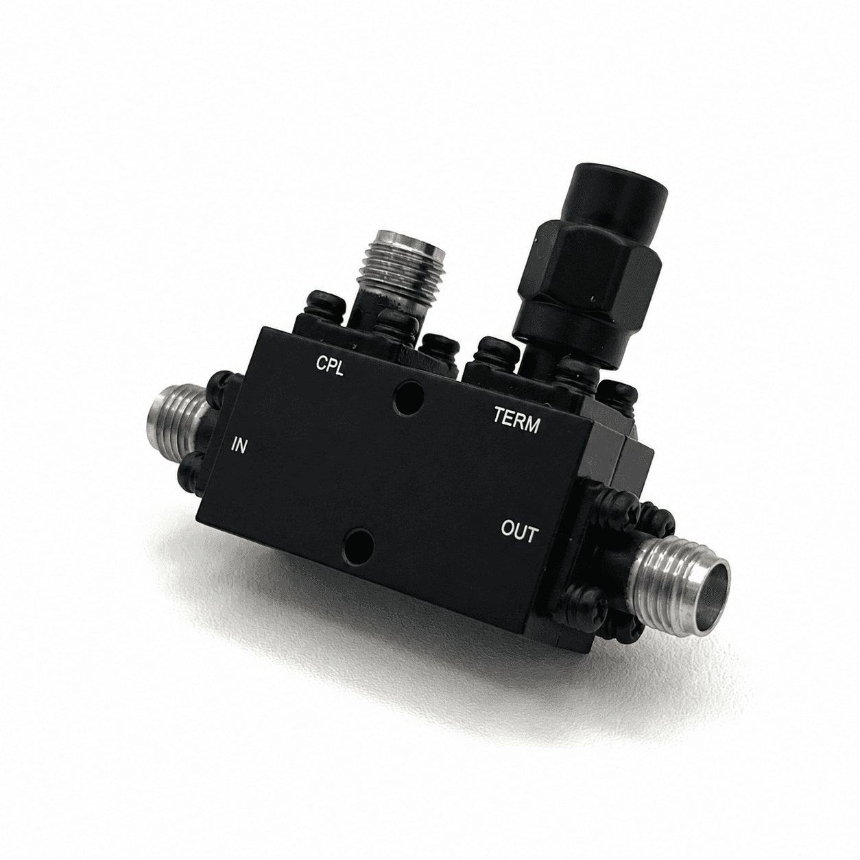
PRODUCT OVERVIEW
At 10 dB this is the tightest coupling in the family, taking the largest sample of the through signal. It suits monitoring paths that need signal at the coupled port, such as a spectrum analyser at the end of a long cable, a power detector or a monitoring receiver. Insertion loss on the through path is 1 dB minimum and 1.5 dB typical, the highest in the family and the direct consequence of the tighter coupling. Directivity is 13 dB typical across the full range. Thirty-two GHz of continuous coverage spans X through Ka band, so a single part serves X-band downlink work, Ku SATCOM and Ka payload testing without swapping hardware. The body is 28 x 15 x 11 mm (1.1 x 0.59 x 0.43 in) at 30 g with 2.92 mm female connectors, rated -40 to +85 °C operating and -70 to +100 °C storage. DC-BB-002 and DC-BB-003 provide 20 dB and 30 dB coupling in the same electrical family and connector standard.
At 10 dB this is the tightest coupling in the family, taking the largest sample of the through signal. It suits monitoring paths that need signal at the coupled port, such as a spectrum analyser at the end of a long cable, a power detector or a monitoring receiver. Insertion loss on the through path is 1 dB minimum and 1.5 dB typical, the highest in the family and the direct consequence of the tighter coupling. Directivity is 13 dB typical across the full range. Thirty-two GHz of continuous coverage spans X through Ka band, so a single part serves X-band downlink work, Ku SATCOM and Ka payload testing without swapping hardware. The body is 28 x 15 x 11 mm (1.1 x 0.59 x 0.43 in) at 30 g with 2.92 mm female connectors, rated -40 to +85 °C operating and -70 to +100 °C storage. DC-BB-002 and DC-BB-003 provide 20 dB and 30 dB coupling in the same electrical family and connector standard.
TECHNICAL SPECIFICATIONS
RF PERFORMANCE
FREQUENCY RANGE
8-40 GHz
COUPLING
10 dB
INSERTION LOSS
1 dB typical
DIRECTIVITY
13 dB minimum
INTEGRATION & QUALIFICATION
APPLICATION
Test/Measurement
TRL
TRL 7
RF CONNECTOR
2.92 mm female
OPERATING TEMPERATURE
-40 to +85 °C
HUMIDITY
SHOCK
MASS
30 g